I had several attempts at making a good soprano uke with a real arched back..I mean "arched" not just a slight radius" that can only be seen if you place a straightedge on it and daylight show's thro' at the end's" .. I wanted an arch of about 4 mm or more in the centre that you could feel when held against you..I recon that the more the back of the uke is not resting again'st your body..the more the volume will be projecting out front thro' the soundhole..I tried the traditional methods of "Radius dishes, Go-Bar decks" etc: they worked, but only slight radius's could be obtained due to spring back... this meant I would have to beef up the bracing to hold everything in place. My sopranos need bracings made of spruce approx: 5.5mm square if i had to beef them up to hold the a 5 ft X 10 ft radius (which is what i was looking for) they would have to be about 12mm high.
~~~~~~~~~~~~~~~~
Now 15ft - 20ft raddii.. for the backs seamed to be standard for most Guitar builders..this is ok on guitars that are about 20" across, but on Soprano ukes that are 6"-7" across you can hardly see the arch, eg: a 20 ft radius on a soprano would only be a .022" arch...... So I thought it was time I took the matters to hand...And this page is about how I went about it.
~~~~~~~~~~~~~~~~~~~~
I recently purchased at great expense a genuine 1930's Martin Style "O" ukulele ..I bought this so I could get accurate dimensions from it..Or so I told the Wife.The truth is I've always wanted one.
Anyway! I did a full dimensional survey of it..
The back plate was indeed well arched and I took a close look at it
with a home made radius gauge...5 ft 2" as near as dammit.
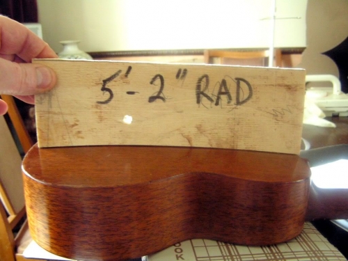
I also checked the back crossways... the back crossways arch was approx: 10ft radius..So I was looking now at a double radius 5ft 2" X 10ft.?????
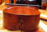
The two cross bracings inside were only about 1/4" square so I new from experience that they alone were not strong enough to hold the back to that shape ..So there was work to done.
~~~~~~~~~~~~~~~~~~~~~~~~~
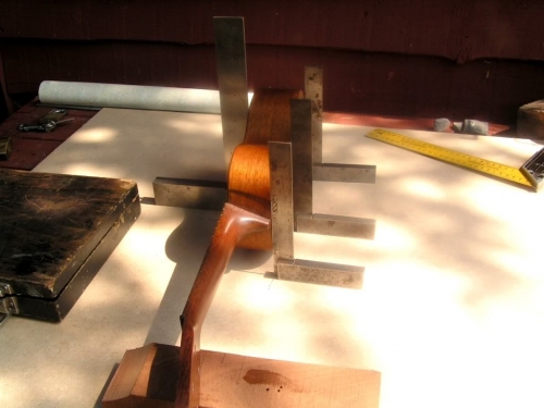
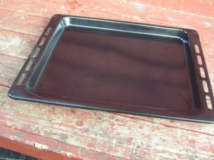
The first thing I realised was to get that kind of arch would require some heat bending..so I set about designing and making a custom back bender..I couldn't find anything on the internet about heat bending backs..So I had do it alone... At the time I had just bought "The Wife" a new oven for the kitchen..the old one that i'd thrown out for scrap, had a nice steel drip tray that i saved to use on my lathe to catch swarfe and stuff...But now I realised that it coud be just right for my bender project.
Now I had to work out how to form it into an arch form.....Well I already had a 10ft radius dish that I made some time ago..so I used that....Years and years ago when I was still a schoolboy I remembered in metalwork class we had a log of wood turned on end with a dish shape carved out on it and we used that to beat copper ashtays into dish shape with an egg shaped mallet....I didn't have and egg shaped mallet but I had a heavy rubber one so I used that instead.
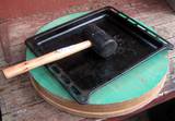
I proceeded to bash the tray into shape using the radius dish as an anvil.
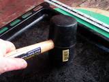
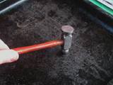
First using the heavy mallet and then a panel beating hammer to knock out the smaller bumps
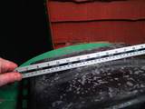
I soon made good progress and it started to take shape, and I took regular checks with a straight edge.
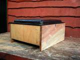
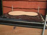
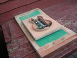
When I was satisfied with the results...I made up a box to mount it on...Like this..(I secured it to the box with 4 screws and washers).
Next the Heat source I had good results with halogen sunflood lights on my Fox Side Bender so I used them again..I mounted them on a base board and wired them up..Then fitted 4 lengths of M8 threaded bar with nuts and washers.
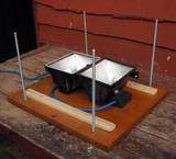
I then dropped the box assembly over the halogens and secured it in place with more wood screws.
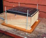
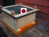
I had to invent something now to hold the uke back in place and apply pressure while the bending took place
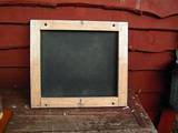
I first thought of.. steel mesh ...or a bag of sand ?? then I remembered that i had some 3 mm thick "Silicon rubber sheeting" I knew that could stand high temperature..so a made up a frame..stapled the rubber sheet to it..Drilled 4 holes at the corners..
made some screw knobs on the lathe fitted them with M8 threaded inserts..and it all went together like this.
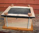
Now it was time to try it out I took a uke back piece placed it on top of the steel former.
Screwed down the lid tight on top of it, and turned on the lamps..The first thing that happened was..the rubber sheet started to baloon..there was nowhere for the hot air to escape ..so i switched it off and took a sharp scriber point and made several puncture holes in the rubber sheet..then I switched it back on and try'd again..this time with more success
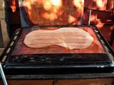
I used a cheap oven timer to gauge how long it should be left to cook..when I saw steam and slight smoke start to billow out of the puncture vents I switched off and let it cool down..About 20 minutes later i took off the lid to see what was what...and suprise!!! it had certainly bent into a dish shape just as I wanted.
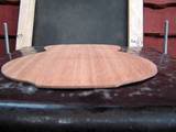
As can be seen when a straight edge is applied.
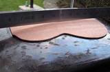
Since these first early experiments i have improved the bending process by adding two 1mm thick copper sheets to sandwich the workpiece under the rubber sheet..thus spreading the heat more evenly..and also i have added an electronic timing device for the lamps.
Here is another bent back with copper sheets..Now I have to make up the spruce bracings and sand them down to a 10ft radius also.
The next part of this Project is about how I made a special "double radius dish"
to achieve the desired arch to transfer to the uke side assembly.
My Son "Mike" came to the rescue now .. He is a bit of a Wizz on the computer and he taught himself
how to programme CNC machines for his own use in his manufacturing business..Now I built a few different styles of CNC router machines for him in the past..I know how to build e'm but when it comes to working on them I'm pretty useless..It must be my age??
So he got on to the computer and with the aid of Solidworks CAD he soon came up with the design of radius dish that I was after....A rectangular block dished 5 ft 2" lengthways and dished 10 ft across.
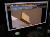
This design was converted to "G" code and all the info stored on a Memory stick and fed into the CNC setup.
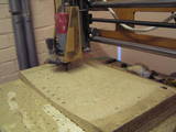
next I got hold of a nice thick lump of chipboard / counter top..clamped it down on the CNC Machine table
and 3D cutting commenced ..and it all went to plan.
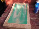
When the machining was completed I took the dish gave it a coat of car body filler to smooth out any machining marks and fill a few holes that were in the board to start with...I could have made this dish the hard way by hand..making up two radiused router sleds..but this was faster.
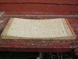
After sanding the filler level
I glued on a couple of 100mm wide strips of 80 grit abrasive paper.
and now final sanding of the profile
A more detailed account of this part of the project,
can be viewed here in this "Photo Slide Show"
And here is the finished job all french polished an waiting for the neck to be glued in.
(I placed a pencil on the back to emphasise the arch)
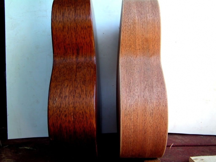
An finally! a picture of a genuine Martin Style "O" back to back with my version of the same.
Thats all for now.