I decided to build a drum/ thickness sander as cheaply as possible and this is how I went about it.
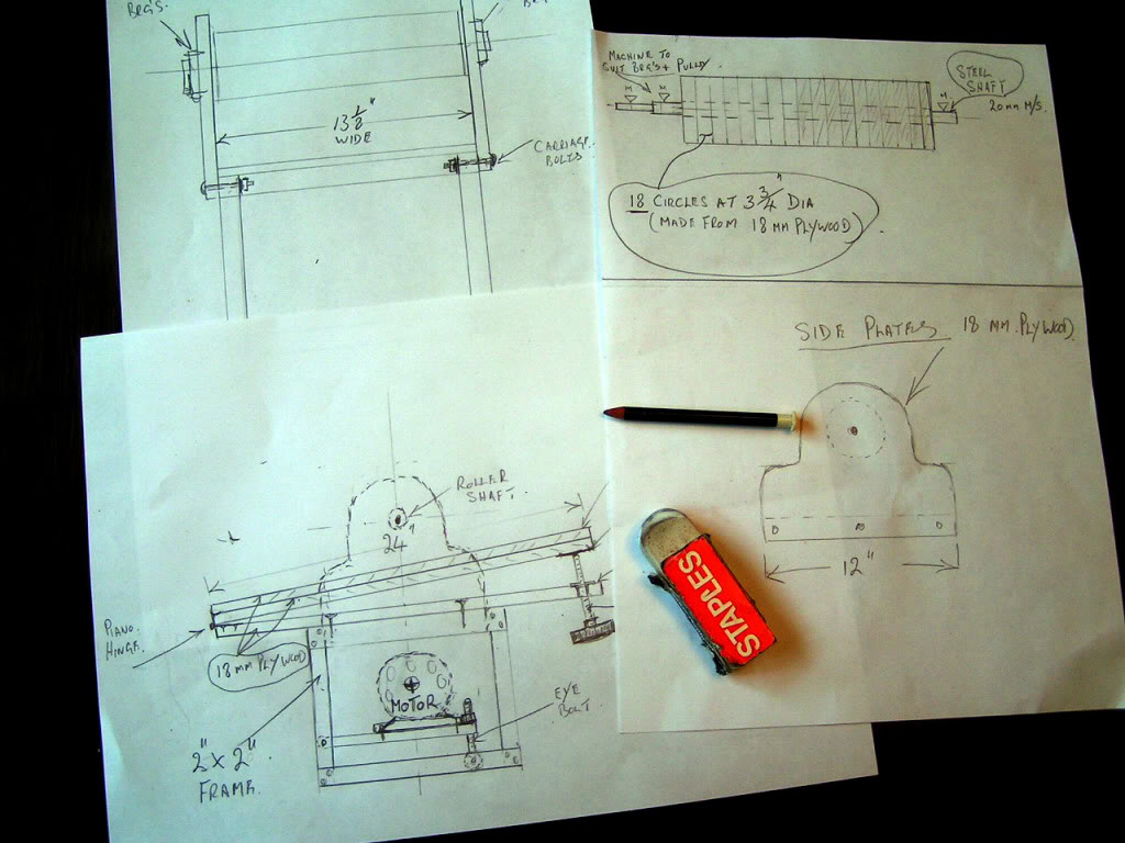
First I made start.. like I always do with a few rough sketches on paper.
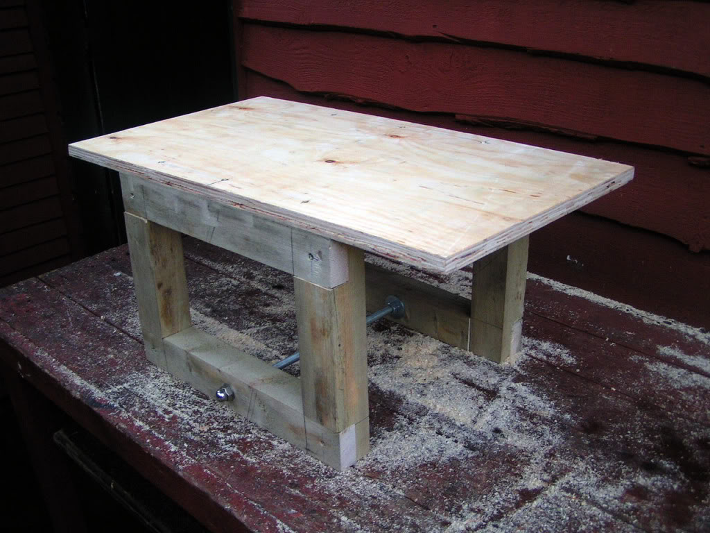
Now I made start this morning with a trip to the local DIY shop..and I bought some 2" x 2" and a sheet of cheap 18 mm plywood..and here is the begining of the Machine...this is to be the base frame..I'm sure you'll
be jealous of my cabinet making skills which were taught me by "Clive" the First fix joiner...the dimensions are 14" X 10".
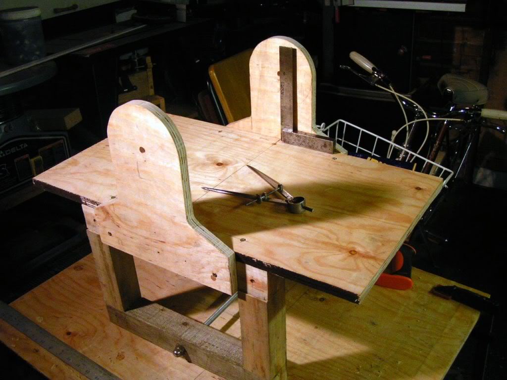
Here we are with the next bit..what do you know, its a table now!..top piece is 13.125 " X 24".. The brace across the bottom is M10 threaded rod c/w washers and nuts...that I had lying around
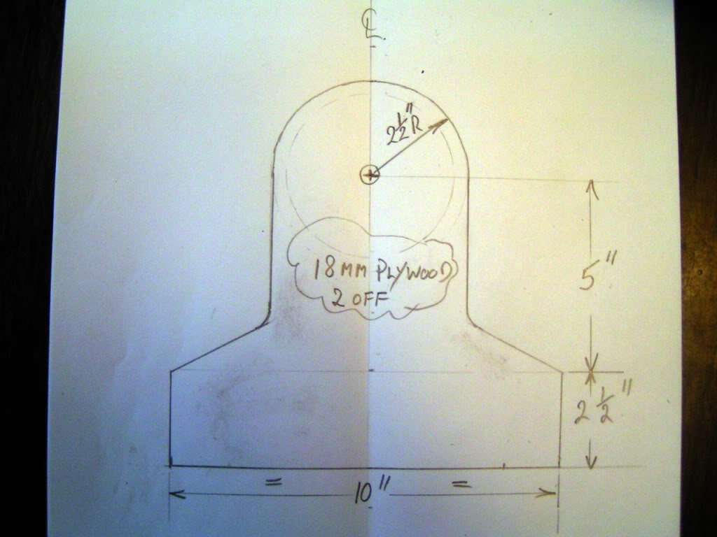
and here's a workshop sketch of the next bit to make..this is easy i'nt it
I soon got those made and fitted.
A few years ago , in a mad moment I bought about sixty catalogue returns faulty 10" angle grinders ..I managed to repair about 40% of them for resale, and the rest I scrapped but before I scrapped them I removed all the bearings for future projects like this one.
This is one of the grinders.
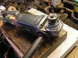
And here are some of the bearings with a couple of "V" type pulley wheels I'm going to use.
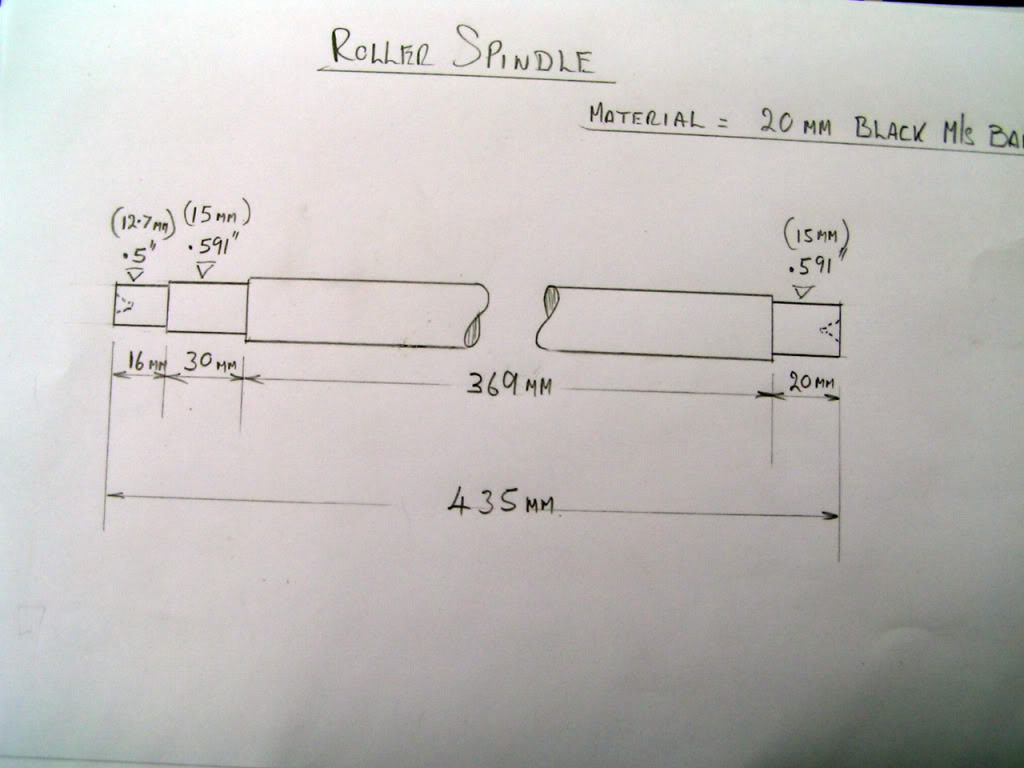
The bearing are for the main roller spindle ..I intend to make this spindle my with the aid of my trusty 13" South Bend lathe.
But first I needed a drawing of the spindle to work to so I took afew measurments of the job came up with this
Next I hacked off a length of seel black bar that i've had in the workshop for years.
and commenced the turning operation.
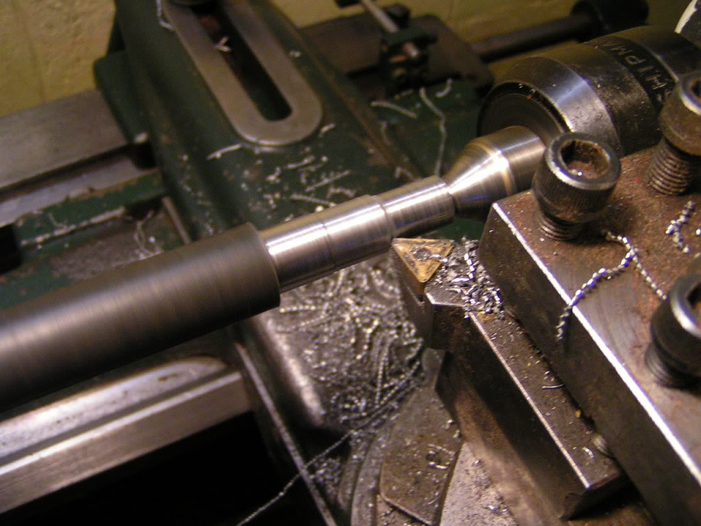
Following the turning of the ends to suit the bearings I gave the rest of the bar a skim to give it balance
when it's spinning in the sander. co' we dont want vibrations as it makes ripples in the workpiece.
Then mounted the spindle in position for a dimensional check.
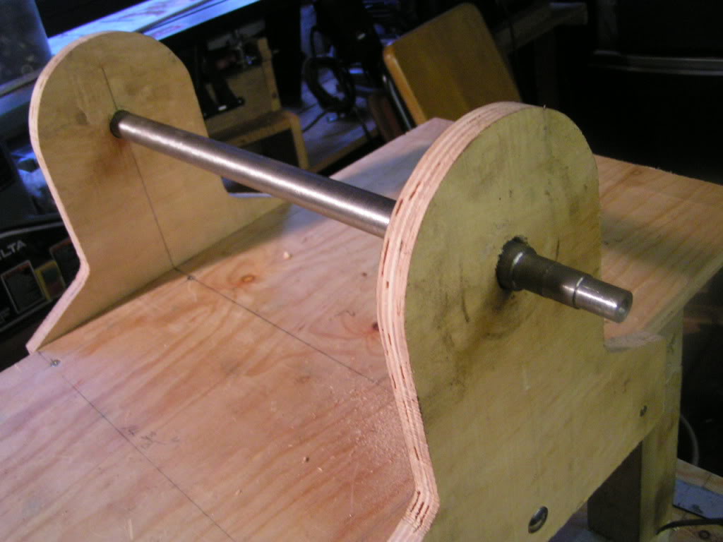
And then checked it withe the bearings and pulley wheel.
Now it's time to make the roller....For this I cut out and drilled some MDF blocks from scrap lying around in the workshop.

I made enough to fill the roller spindle.
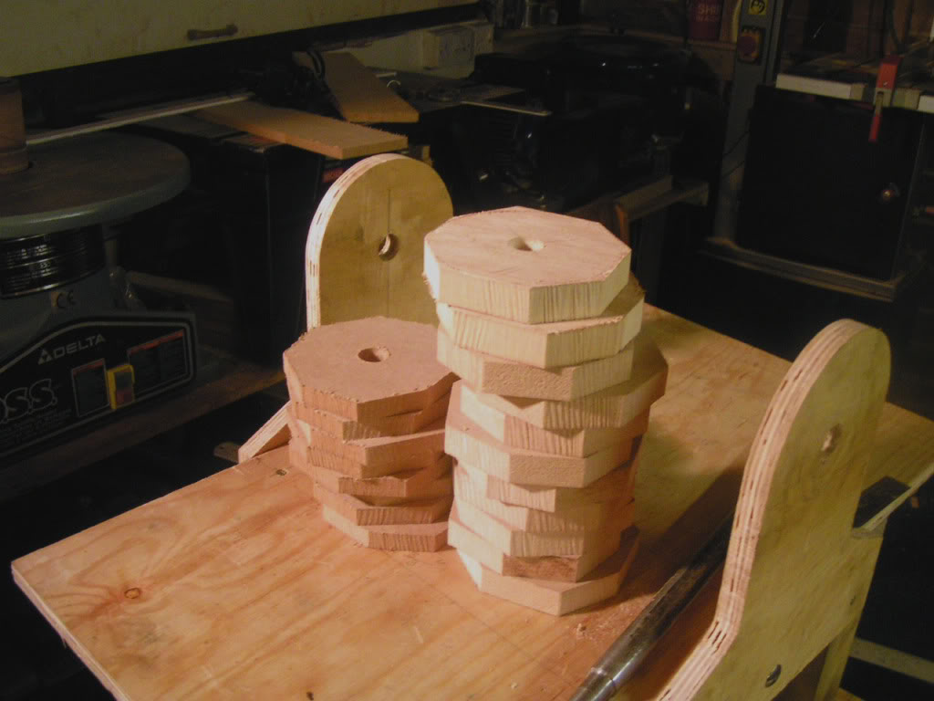
Now I commence to glue all these together in position on the spindle.
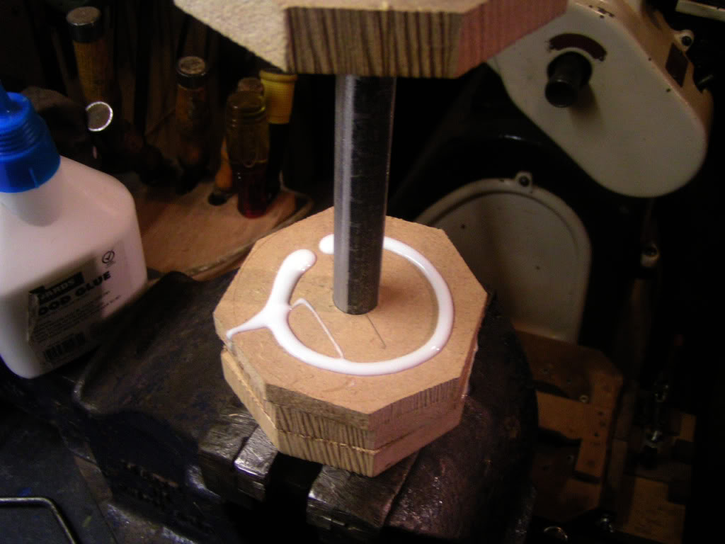
When all the blocks were glued up on the spindle I clamped them all together and left them all night to set.
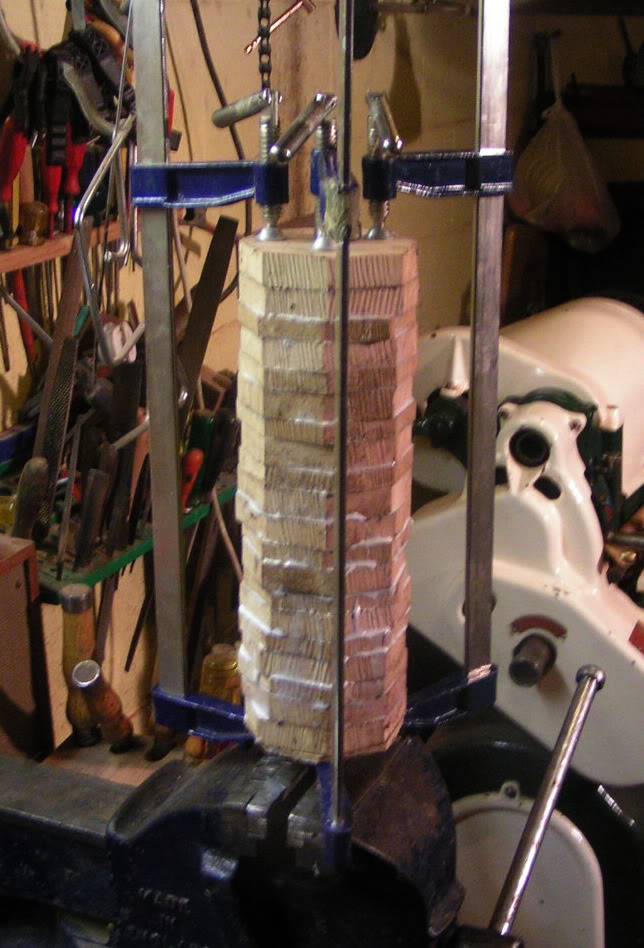
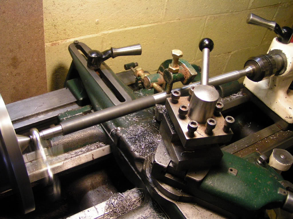
Next day I removed the clamps and set the whole assembly back into the lathe to start to machine the roller surface level.
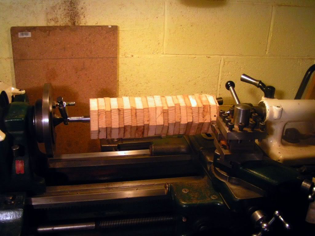
And machining begins.
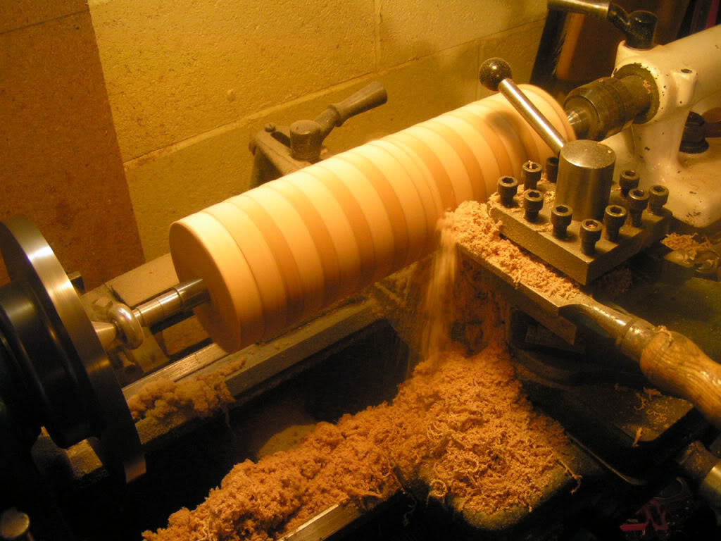
When satisfied with the finish it given a good once over with 120 grit sanding paper.
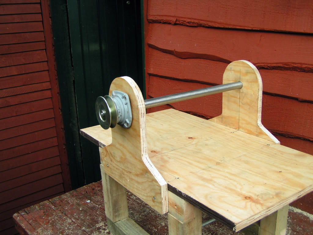
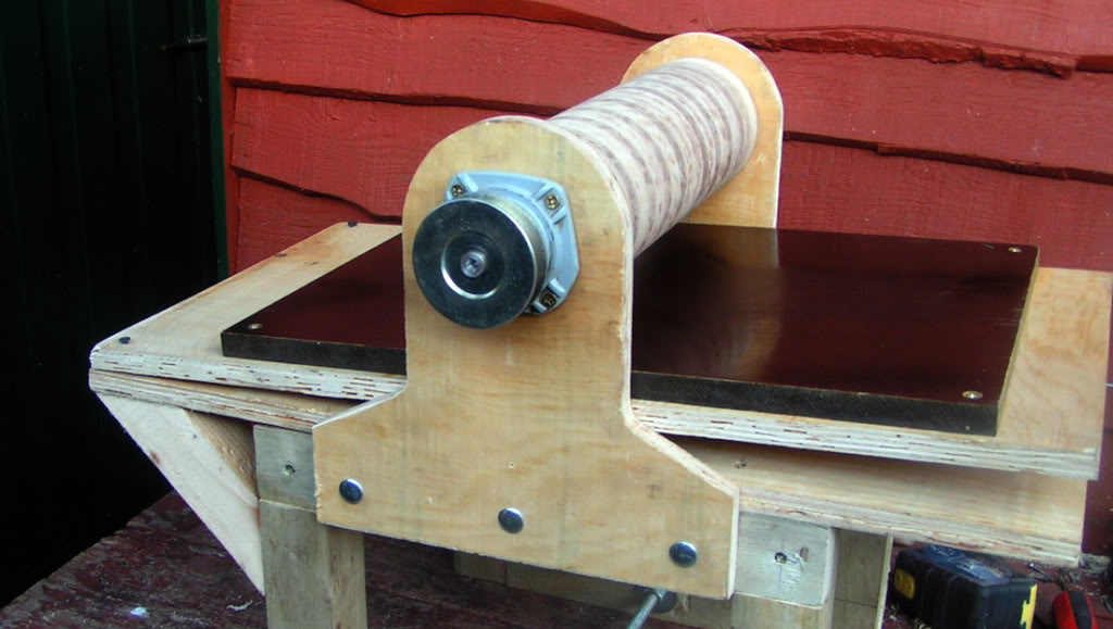
Now I mount it into position in the main assembly...set it level and secure the bearings..and fit the top pulley.
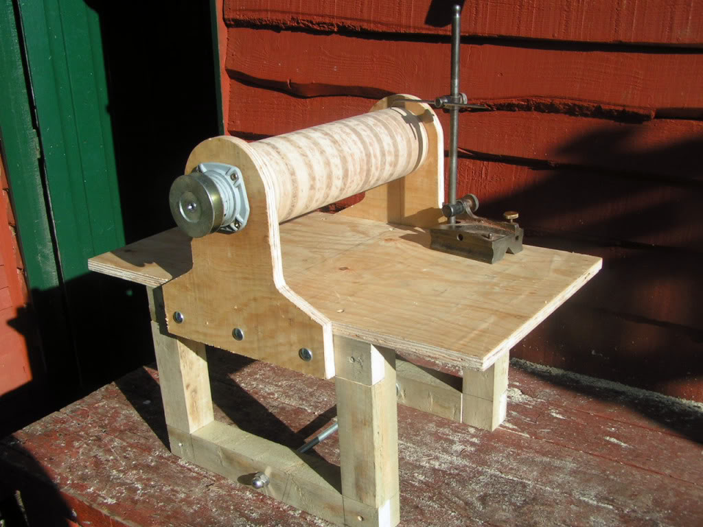
I had a nice chunk of tuffnel laying around in the workshop waiting for a use..I rescued this from a skip years ago knowing it would come in handy one day...so I mounted this on a plywood board and it will be ideal as the base board for the sander.
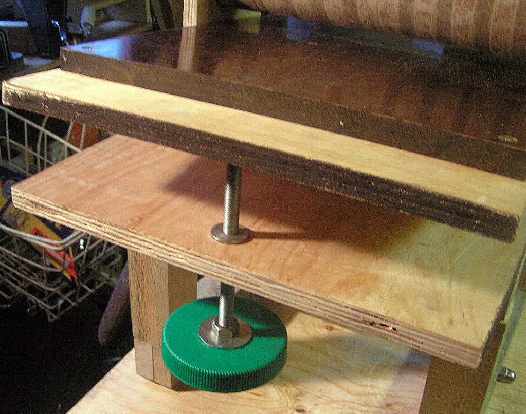
Next I got together a few bits out of the scrap bin and Kitchen...One M10 T nut (made on lathe)...One 6" X M10 threaded rod...two Penny washers.... and two M10 nuts...and a fruit jar ????
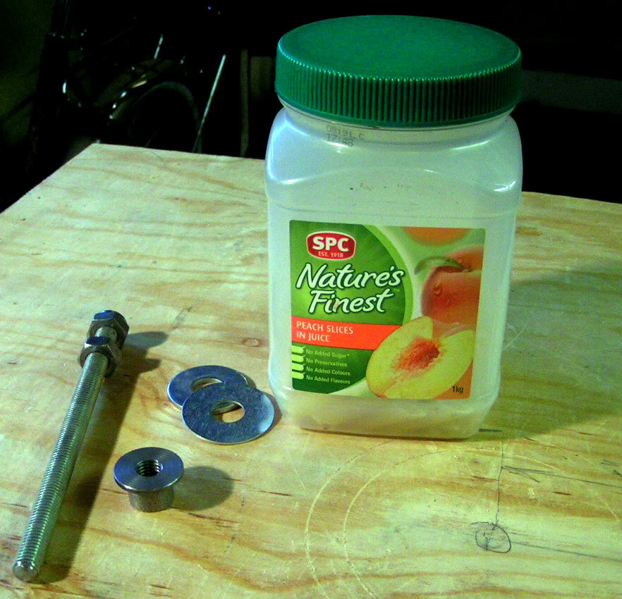
Now i get rid of the Jar but keep the lid.....Put the pieces all to gether like this.
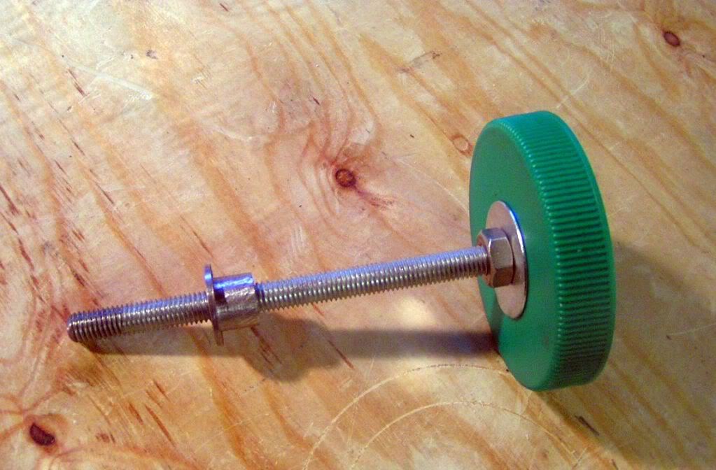
When it's fitted to the main assemblyit become a great inexpensive fine adjustment control.
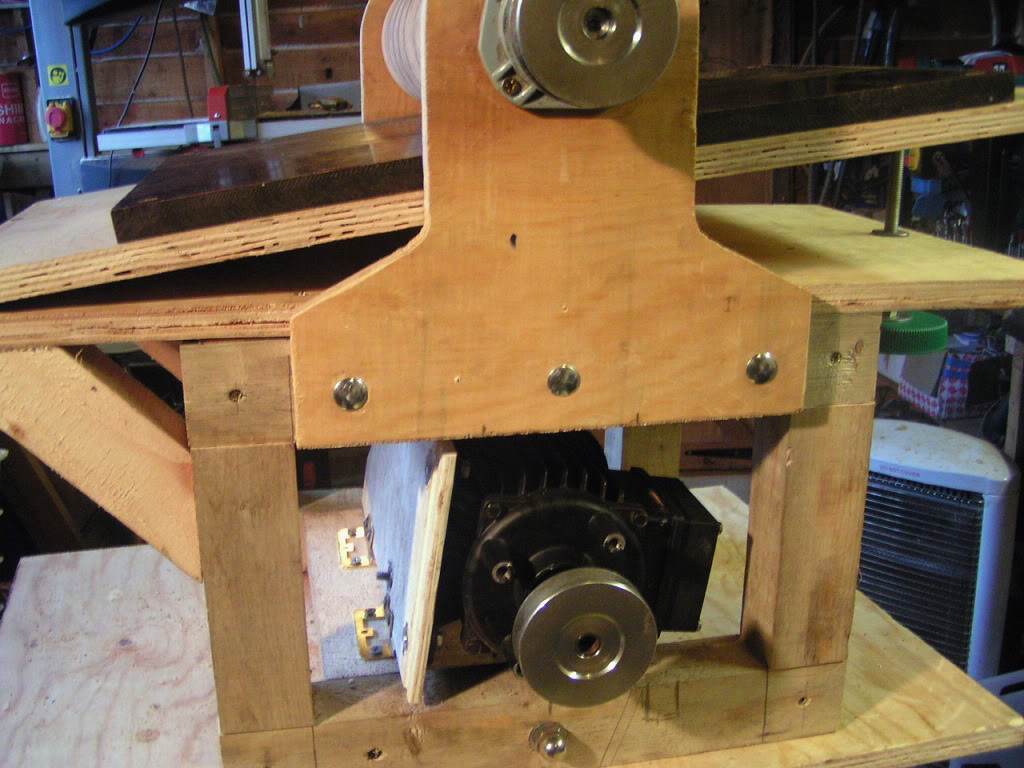
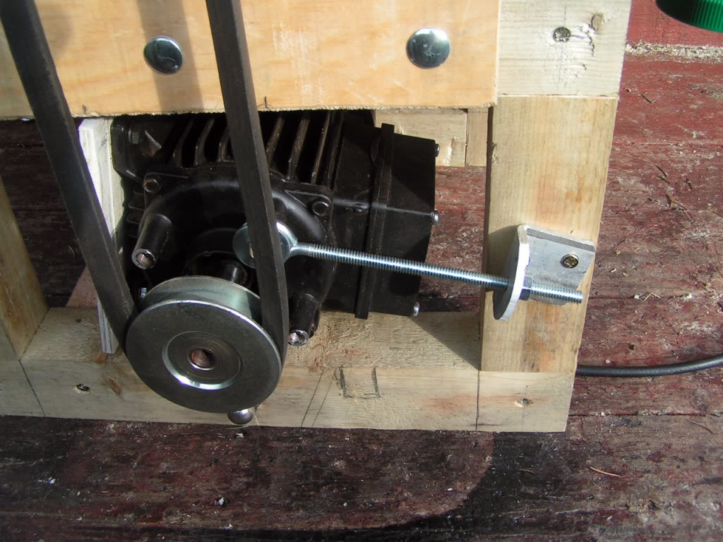
The motor is now mounted underside the frame this is and old 1/2 HP shower pump motor with the pump unit removed and the pulley wheel added.....I got the measurments wrong somewhere at this stage and the motor didn't fit horizontaly as it was supposed to, due to the capacitor box on top of the motor... so I ended up mounting it sideways on a hinged board to make it fit.
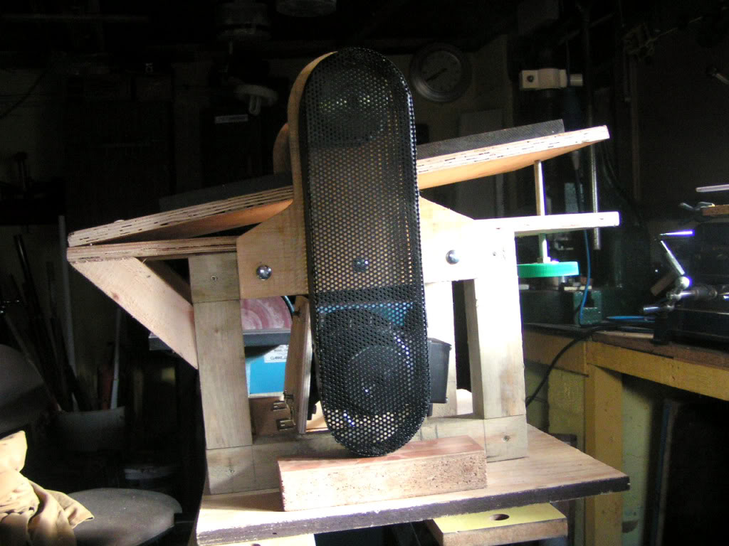
Now's the time to think about "health and safety" with those pulley wheels and V belts and roller spinning around at high speed bwe don't want to get our finger or anything lose caught in there
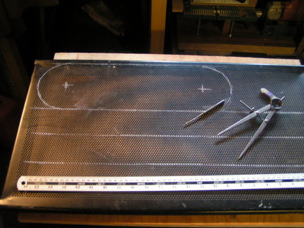
so it's time to make a "safety guard"....Some years ago i bought two computer desks the were made of steel tubing with several shelves all made from perforated steel..if you've ever purchased perforated steel sheet then you'll know how expensive it can be..so when I finally got rid of the desks I kept hold of the shelves..I have made a few machine guards from this material already, and I stilll had enough left over for this job.
First I got out the Marking out tools took a few measurments around the pully's and marked out the sections i needed.
Then i got out the metal shears and did a bit of scissor work.
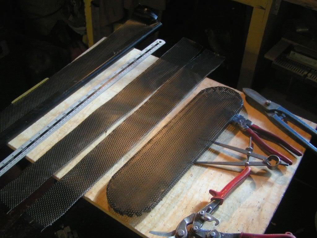
After a bit of bending, bashing, bashing, drilling, and pop riveting....Known as "sheet metal working"
I came up with this....Trial fit shows irs spot on.
Now I fit the belt and tensioner..the tensioner is just a M6 eyebolt mounted on an angle bracket...the belt is a car fan belt.
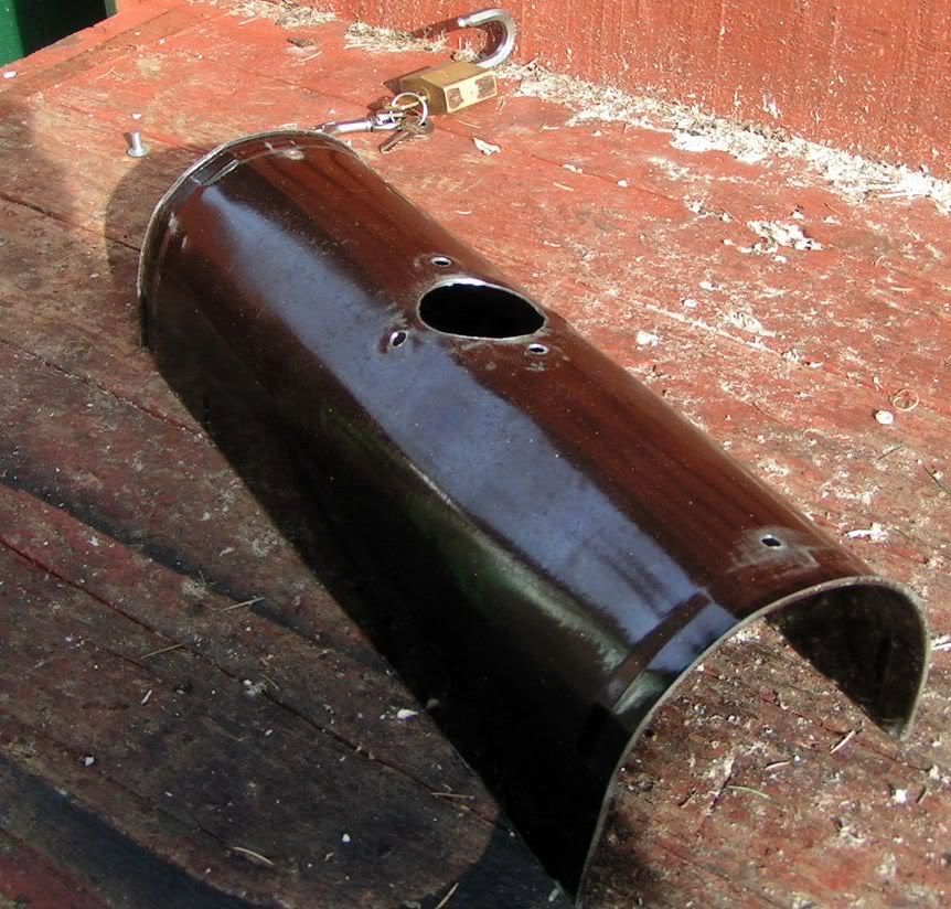
One thing that drum sanders do best of all is make dust (loads of it) so now it's time to design the dust extractor...Good news..a Neighbour has put an electric oven out for the scrapmen ( Irish Tinker types) ..I asked if I could have a bit off it and he said "By all mean's old Chap no problem" so I removed one of the lining plates from inside..now I have the material for the Dust Hood ...stove enamel" finish as well.
and this is what I made from it with the help of a tree in the garden that I bent it round.
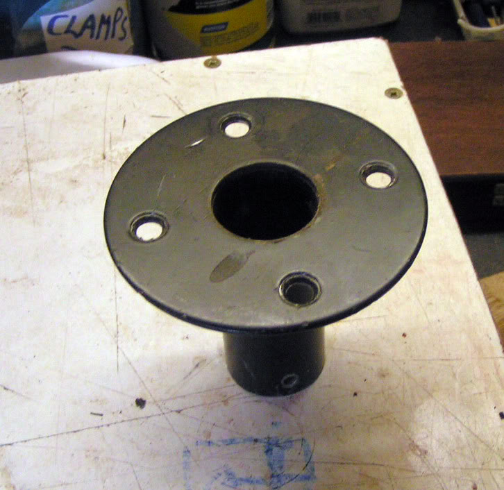
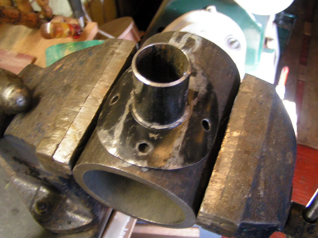
Next I needed a nozzle for the shop vac to connect to...In my scrap box I found an ideal thing for the job
It's called a "Top Hat" its used to mount PA speaker cabinets on poles.
I got out the big hammer and a chunk of heavy walled pipe and volently beat it into shape to fit the hood..
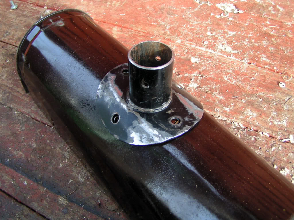
went the noise had subsided and my ears stopped ringing it looked just right.
And here it is placed in position on the hood.
I used two 50mm lengths of M6 threaded bar to secure the hood to the side plates ..I drilled a couple of 5mm holes in the top of the side boards, ground a taper on the threaded bar and with two M6 nuts locked against each other, I screwed them in, with a bit of CA glue to help...fitted a couple of wing nuts .. and "Bob's yer Uncle"
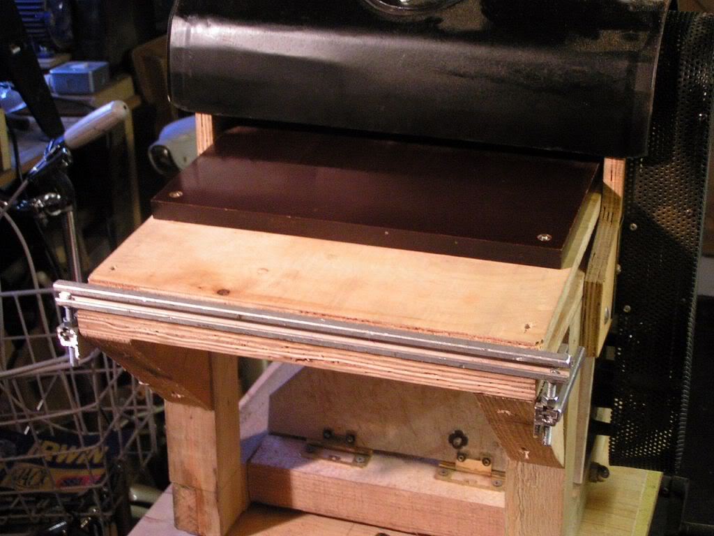
For the sander to be accurate and produce wafer thin soundboards it is essential for the baseboard to be parallel to the roller drum..I achieved this by fastening a strip of "Rack Strip" along the front edge of the base board ..angle will do the job just as well, but I didn't have any in stock...I then mounted a couple of jacking screws at the outside edges.. these were just made out of M6 threaded bar and a couple of locking nuts.
These jacking screws adjust the base board untill it matches the surface of the drum.
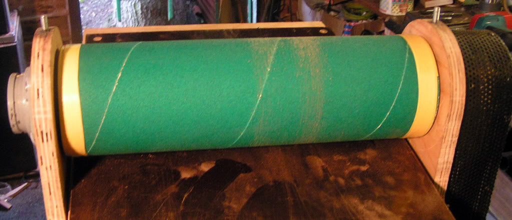
Now it's time to load the drum with abrasive..I got this material from the local DIY store (B & Q) I find 80 grit is the best overall abrasive size to use on drum sanders..I find that drawing pins and electricions tape is the best way to fix the abrasive to the drum.
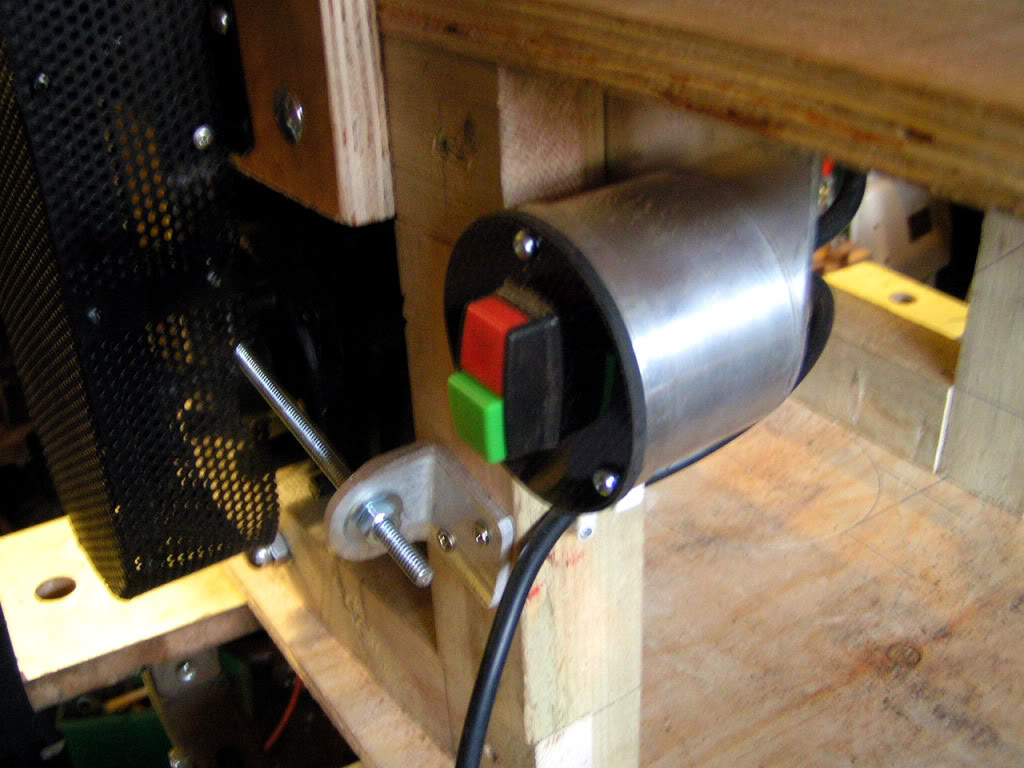
Now for the electrics..I purchased a cheap "stop start switch unit" from E-bay and mounted it in a handy place on the maqchine3...
I used a piece of aluminium tube and a piece of plastic to mount it....the wiring up of the motor to the switch was not a problem to me co's I worked in electrical engineering for part of my working life ..But if your not into electrics.. I recommend you find someone who know's how to do this job.
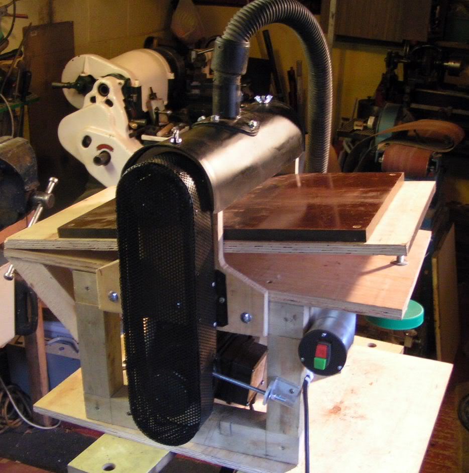
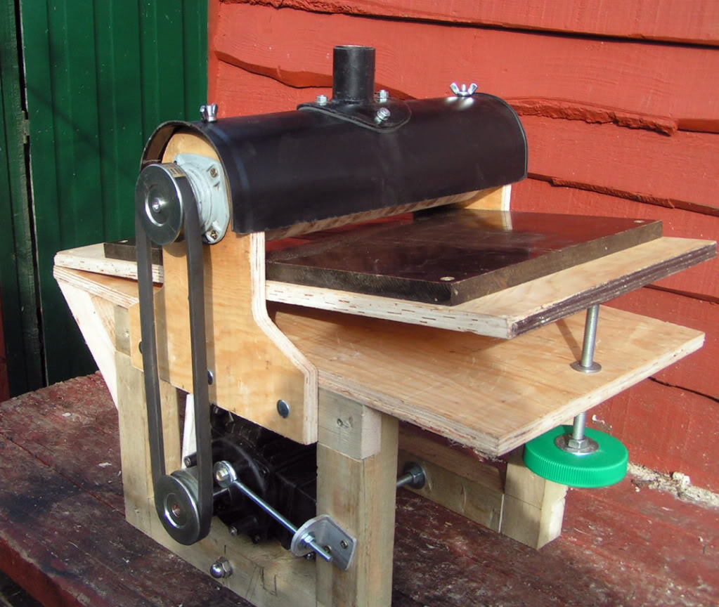
Well thats about it for the "Thickness sander Project".. I made about 150 ukuleles with this machine before i upgraded to a "commercial drum sander"..this is the finished machine with shop vac fitted...So if you you want to make one.....Go for it !